Before starting the ballast install I located 3 sets of wires tucked up under the transom lip in the back of the boat. They were heavy 10 gauge wires in 3 pairs. These were obvious factory wiring for the ballast that was never installed in my boat. I planned to use 2 of these sets for the new Johnson pumps.

This is a picture looking down the side of the boat (under the gunnel) while laying in the driver footwell area. If you notice in the wiring bundle near the top left corner you can see the same heavy gauge wires that we found in the rear of the boat. These come forward to the switch panel. 

Here is a picture of those same heavy gauge wires coming from the rear of the boat (6 heavy gauge ones plus a few others). They already had slot connectors on them and were all bundled up together.
Here are the same 6 heavy gauge wires from the back of the boat now separated out and ready for wiring. (I only used 2 pairs and tucked the others back away for some other project)

Here is a picture of the fuse block under the driver console. On the right side you will see a separate area that has label for port, starboard, and center ballast, as well as tower lights. These all have the heavy gauge wire on them already. These wiring colors match the wires that come from the rear of the boat. There are a few fuses missing for the starboard ballast and center ballast. I followed these wires (not easy to do) and they took me to some white relays. See 2nd pic.

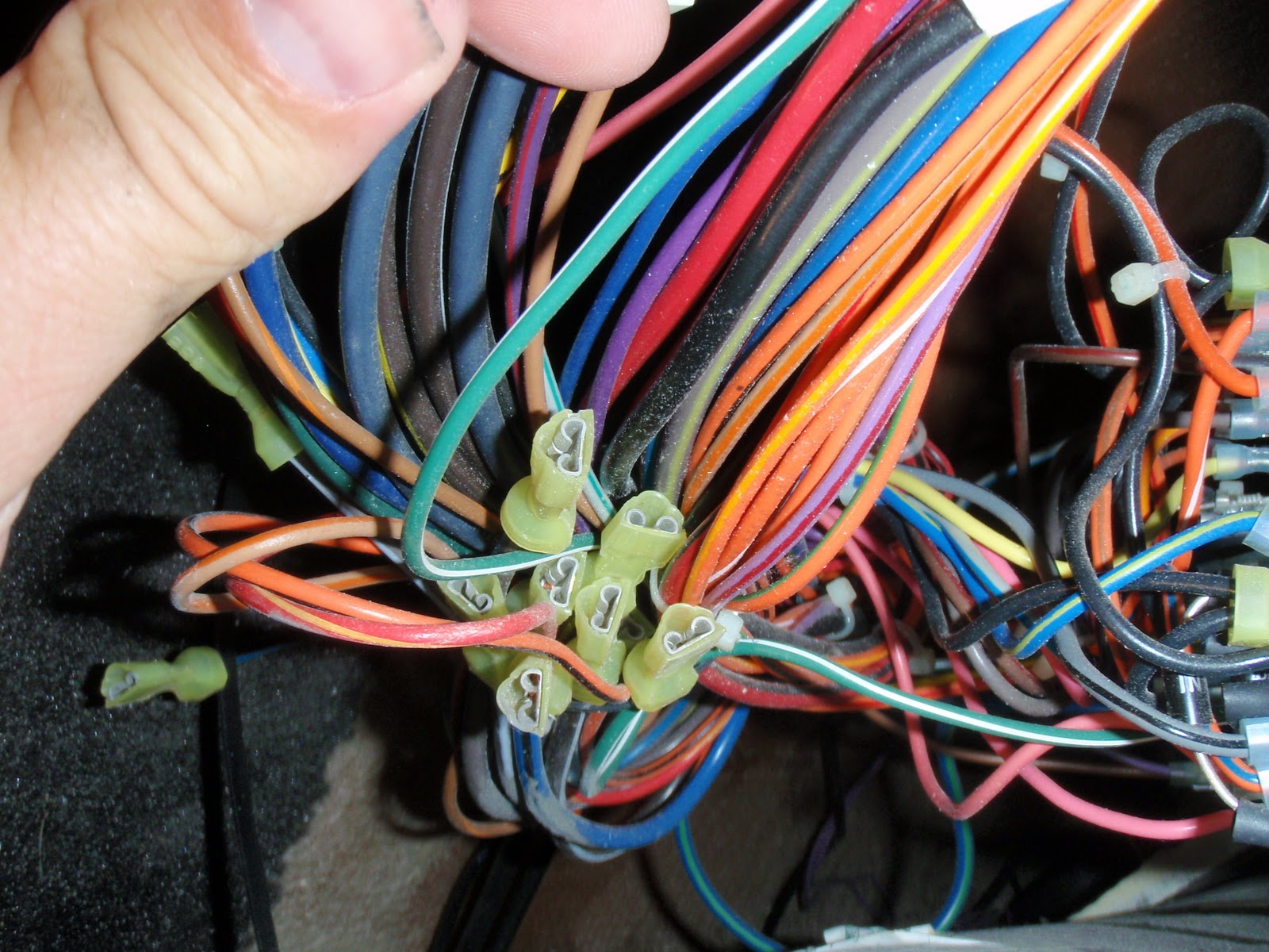
These are the white relays that the wires from the fuse block go into. I was able to follow them through the other side of the relay and then to an area behind the switch panel where they were bundled together with slot connectors on them.

So all the wiring was in place except for there were no ground wires coming from the fuse block. Only hot wires. So I obtained some 10 gauge wires and ran two wires from the grounding slots on the far left of the fuse block (see fuse block picture above) to the rear of the switch panel. I used green wire because its all I had. The fuse block picture does not show the green ground wires yet. The following picture shows the switches that came with the Johnson pumps. I did not like how they looked because they did not match the factory switches. But I tried to use them anyway. I got them all wired up and they worked great..... However they did not fit into the slots of the switch panel board.

So I ordered factory switches from Fineline. Shell was a big help there. These are what the starboard and port factory switches look like that match my other switches.


Unfortunately the switches from Fineline have the incorrect wiring pins in the back of them for use with a reversible pump like the Jabsco or Johnson pumps. These switches are designed to be used through a relay of some sort and use a ballast puppy to fill and mayfair pumps to empty. Here is what the pins on the back of the factory switches look like. There are only 5 pin connectors.

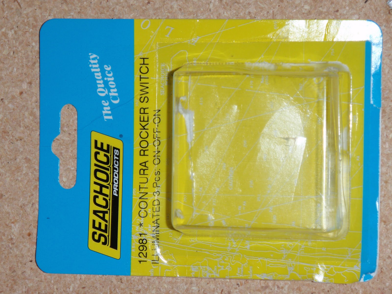
So I decided to order some different switches. I found these switches on Ebay at a store called The Boating Mall... http://stores.ebay.com/theboatingmall . I took a picture of the switch packaging so you have the correct switch number and everything. These are double pole double throw (DPDT) switch that also has the LED light on them. They are generic switches with generic face plates with no writing on them. They do fit in the holes in the centurion switch panel. So what I did is pop the face plates off of the switches I purchased from Centurion and swapped them with the face plates on the switches from Ebay. So now i had the correct switch body and now also had the matching factory face plate with the correct ballast text on them. Here is the switch packaging. It is a Cortura rocker switch number 12982. Make sure and get the illuminated one if you want the LED lights to work.
Here is what the back of the new switches look like. There are 7 pins.

Now for the switch wiring. There are 7 pins on the rear of the switch. There are 3 in the left column and 4 in the right. They are numbered as follows: The top left is 1, the middle left is 2, the bottom left is 3. The top right is 7, the 2nd on right is 4, the 3rd on the right column is 5, and the bottom right is 6. So here is how I wired mine. Hot wire from the fuse block goes to 5. Ground wire from the fuse block goes to 2. Run a loop from 2 to 7 to get the LED light to work. Run the wires that are going to/from your pump to 3 and 6. Run a loop from 3 to 4 and from 6 to 1 (this steps allows the pump to reverse). Hopefully that works. This next part is kinda complicated. Now you have to test the switch and pump. At this point I disconnected my ballast sacs and filled a 5 gallon bucked with water. I put the hose to the ballast sac into the bucket. I then hit the fill switch. If hooked up correctly the hose will blow bubbles into the water (sucking air from the intake and pushing it into the water. If that happens then great. Then hit empty. If hooked up correctly then water should start sucking from the bucket and coming out the bottom thru hull. If this happen great!!! If just the opposite happens (sucking water with fill and blowing bubbles when empty) then you need to reverse wires 3 and 6 and their corresponding loops to 1 and 4. That will fix that problem. The other potential problem is if the empty LED light comes on when you hit fill and visa versa. If this happens pull the switch out of the panel. Pop off the face plate and turn it over and pop back on. Then put switch back in the panel. So essentially you just turned the switch upside down. That will fix the LED light problem. Here is a picture of the wiring of the back of the switch. Make sure and buy big enough wire diameter connectors so that on several of them you can push 2 wires in them before pinching them down (pins 2, 3, and 6). In this picture the green wire is ground from fuse block to #2, Reds are loops from 3 to 4 and 1 to 6, Thin black wire is loop from 2 to 7, Large black wire with blue stripe is wire from pump as is the large darker brown wire (hot and ground does not matter here. You just want the pump to spin the correct way for fill and empty), the light brown wire with a blue stripe is hot from fuse block.

Here is the butt connectors I used to connect the factory wires near the rear of the boat to the pump wires. I used liquid electrical tape (red stuff) to make the connections waterproof. The wire was then put inside the plastic black spiral conduit and taped shut with electrical tape.

Here is the finished switches in place. Looks clean and just like a factory install!

No comments:
Post a Comment