The purpose of this blog is to create a place to compile all of the information and pictures that I have from designing and building my ballast system. Hopefully this will allow all this information to be just a "click" away for my boating friends or those just wanting to build a ballast system. I realize there are many ways to build a great system. This just happens to be the way I did it. I'm not saying its the greatest way but it turned to be just as awesome as I dreamed it to be!
This ballast system is for a 2003 Centurion Avalanche. The ballast system will be used primarily to create a surfing wave on the port side of the boat. However this particular set up can be easily modified to design a ballast system for the starboard side of the boat or for a more equally balanced ballast system for wakeboarding. The boat currently has no factory ballast system so I am basically starting from scratch on this one. If your boat has some hard tanks already installed the process can be much easier
My current surfing set up includes using 4 fat sac’s that I manually fill with pumps that are powered from the 12 volt accessory outlet. The current sac’s are 750# in port locker, 500# on rear seat toward port side, 175# under port seats, and 175# on port seats for a total of 1600#. It takes about 20 minutes to fill all these bags and other 20 minutes to empty them.
The new automated system will fill the new sacs with a push of 2 buttons on the switch panel and should both fill and empty in less than 10 minutes. The new system will utilize a custom made Flying High Pro X fat sac that is designed to completely fill the entire port locker and then continue forward under the port seats. The dimension and weight of the custom sac is as follows:
Main 22H X 24W X 52L
Arm 10H X 24W X 62L
Main… LXWXH = 27456 = 118.857 gallons = 992.46 pounds
Arm.. LXWXH = 14880 = 64.416 gallons = 537.87 pounds
Total cubic inches = 42336 = 183.272 gallons = 1530 pounds
*Water 8.35 pounds per gallon
I am using 2 reversible Johnson Ultra Ballast pumps (13.7 GPM) to both fill and empty the custom sac. I chose these pumps over the Jabsco Ballast Puppy pumps that flow at only 9 GPM. The advantage (which is controversial by those that prefer the aerator type pumps) of the reversible pump is that you can use the same hole in the bottom of the boat to both fill and drain the sacs. This means less holes in the boat!
There are many arguments over using an impeller type pump vs a aerator type. The aerators are cheaper, quieter, and draw less power. The impeller type are more heavy duty but noisier and draw a lot of power. If you want help choosing which is best for you, read this ballast thread... http://www.centurioncrew.com/Aerator-Pumps-and-Electric-t1970.html
This guy tests out the most common type of pump and incorporates different valves as well to see how they effect flow. Some really great hard core info here on pump and valve performance. This data came out after my install was done. I am glad I chose the Johnson pumps and did not utilize any sprinkler valves in the system.
For my water intake, I am using a 1 ¼ inch thru-hull scupper (brass) that will be installed in the bottom of the boat near the speed wheel and T handle floor drain. The 1 ¼ inch inlet/outlet should be sufficient to allow two 1” lines to be run (one to each pump) and allow the pumps plenty of water flow as to not be starved for water. The pumps themselves only have a 1/2” inlets/outlets and the fat sacs only have ¾ inch drain/fill holes. So there are other natural bottlenecks in the system other than the intake.
This ballast system will have two auxiliary fill hoses that will allow other auxiliary sacs to be filled when needed/wanted. These sacs can be placed on the rear seat, port seat, walk through, bow area, or floor area as needed. The two hoses can be pulled out of a compartment to fill/drain the aux sac and then disconnected from the sac and stowed in the compartment.
The custom sac will also have a vent/overflow drain. This will be connected by hose to a 1” stainless steel thru-hull vent on the port side of the boat and will utilize a one way (spring type) valve inline to prevent water from entering into the sac from lake. Once the sac is full this will overflow indicating that the pumps need to be turned off. This will also allow any excess air in the sac to be “burped” off. When emptying the sac the one way valve will not allow any air into the sac and it should raisin up as it drains which is nice to preserve storage space.
Schematic drawing of ballast system as well as an itemized list of plumbing supplies and their location in addition to how many of each are needed. *The sac’s are not to size or shape*.
Double click on any photo to enlarge it.
Drawing of the Custom Avy sac used to place the order
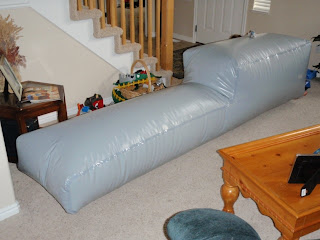
Picture of the custom Avy sac blown up with air. Its HUGE!!!
Saturday, September 19, 2009
Friday, September 18, 2009
Supply list
Plumbing
1 - 1 ¼” bronze thru-hull scupper (West Marine)
1 – 1 ¼” brass ball valve (Lowes)
1 – 1 ¼” PVC threaded to slip adapter (Home Depot)
1 – 1 ¼” piece of PVC (about 1 foot) (Home Depot)
1 – 1 ¼” PVC “T” (all slip connections) (Home Depot)
2 - PVC 1 ¼” slip to 1” thread adapter (Home Depot)
12 – 1” PVC threaded to hose barb (HB) adapter (Home Depot)
40 feet multi-flex 1” I.D. hose (Evco House of Hose) Used 090-1 hose
2 – Johnson Ultra Ballast reversible pumps (13.7 GPM) (maxwake.com)
2 – 1” “T” hose barb connector (Home Depot)
4 – 1” PVC ball valve (threaded) (Home Depot)
3 – Flying High Flow-rite quick connect elbow (W746) (maxwake.com)
3 – Flying High Flow-rite quick connect sac valve threads (W743) (maxwake.com)
1 – Launch Pad “link” connector (Ordered from Launch Pad)
1 – 1” hose barb to male garden hose adapter (Home Depot)
1 – Blue magic perfect union water bed connector (purchased online)
1 - 1” inline check valve (spring type) threaded. (Lowes)
1 – 1” stainless steel thru-hull side discharge (West Marine)
30 – stainless steel hose clamps (3/4” to 1 ¾” size) (Home Depot)
4 – 1” PVC 90 degree elbow hose barb connectors (Home Depot)
Electrical
4 - 10 gauge wire, 8 feet long, all different colors (Home Depot)
1 - 10 gauge wire, 5 feet long, black (Home Depot)
2 - mini fuses, 25 amp (Checker Auto)
6 – butt splice connectors for 10 gauge wire (Home Depot)
10 – insulated female push on connectors for 10 gauge wire (Home Depot)
1 – 20 feet split loom plastic electrical conduit (Home Depot)
3 – rolls electrical tape (Home Depot)
1- can of liquid electrical tape (Home Depot)
10 – 8” zip ties (Home Depot)
10 – 8” mounting zip ties (Home Depot)
8 – ½” long (size 10) stainless steel screws (for mounting zip ties) (Home Depot)
Other supplies
Painters masking tape 1 roll (Home Depot)
Black sharpie pen
1 5/8” hole saw (Home Depot)
1 ¼ “ hole saw (Home Depot)
Safety glasses (Home Depot)
Dust mask (Home Depot)
Rotary sander drill bit or dremel tool
Shop vac
Razor knife
Heat gun (Home Depot)
Bench vise (Home Depot)
¾” cheep paint brush
Small paper cup
Dish soap
Screwdrivers
Hex screw driver for hose clamps
Acetone (home depot)
Marine sealant 3M 5200 fast cure 1 tube (home depot)
Rags for clean up
PVC cement (Home Depot)
Hack saw (Home Depot)
PVC cutter (Home Depot)
Teflon pipe thread tape (2 rolls)
4 – size 8, 1/2” flat head stainless steel screw (for thru-hull scupper) (Home Depot)
8 – size 12, 1 ½” pan head stainless steel screws (for pump mounting) (Home Depot)
24 – ½ inch stainless steel washers (spacers so pump screws don’t go through wall) (Home Depot)
2 - dash switches, double position/double throw (DPDT) (ordered from Centurion)
I listed the places I bought items from or ordered them from online. There are many great vendors out there for many of the items. Search around for good prices and use whoever you would like. Since doing this install I have found Wakeoutlaws to be a great place to shop and they are great supporters of Centurion boats. http://www.wakeoutlaws.com/
Thursday, September 17, 2009
Hole in the boat #1!!! Installing the side vent
This is probably the hardest part of the project. Boats are not meant to have any holes in them. Holes make boats sink. Get over it! Some say that a couple beers make this easier but I am not sure how straight it makes your holes!
You need to decide where to put your side dump hole. Check it out from both the outside for cosmetics and the inside for adequate spacing and access. If you already have a bilge outlet you can use it for reference.
I used a 1 inch stainless steel thru-hull side dump that I purchased at west marine. On the inside it has a hose barb for 1” ID hose. I had several size hole saws and I cut some test holes in a piece of wood to see what size was the tightest fit. The 1 ¼” hole saw was a very tight (too tight) fit but I chose it because the next size up was too big. After drilling the hole I used the rotary sander bit to make the hole just a smidge bigger. More on that later….
So once you have chosen your hole location and hole saw size, mask off the area with painters tape and mark it with a sharpie. Put on safety glasses and dust mask. Make sure you have adequate clearance on the inside for when the drill bit breaks through. Begin drilling with the hole saw in reverse and continue in reverse until well through the gel coat and into the fiberglass. This is to prevent the hole saw from binding or grabbing and cracking or spidering your gel coat. Don't press too hard. You can finish drilling the rest of the hull either in forward or reverse.
Once the hole is made use the rotary sander to radius (not sure if this is the correct term) the edge of the hole where the gel coat is. Essentially sand the gel coat edge back so it’s a small rounded edge with no sharp transition to prevent any future cracking/spidering of the gel coat. Try the thru hull fitting for size and rotary sand the hole if needed to get a good fit.
On the inside use a razor knife to trim the carpet well away from the hole to allow room for the nut to secure the fitting.
Once finished use a shop vac for clean up. Clean the new hole with acetone to prep for sealing with marine sealant. Coat the back edge of the thru-hull and some of the threads with the 3M 5200 marine sealant and seat in hole. On the inside put more sealant on to fill any gaps in the hole. Thread on the mounting nut and tighten. Wipe any excess sealant away and clean any remaining extra with acetone.
Masked and marked ready for drilling
The first hole with edges radiused
The hole from the inside with carpet cut back
The drill bit sander used to radius the edge and enlarge the hole
The thru-hull in place
From the inside with nut in place
Wednesday, September 16, 2009
Hole in the boat #2.... Installing the thru-hull scupper
You need to decide where to put your bottom thru-hull scooper. Check it out from both the outside for cosmetics and the inside for adequate spacing and access. The brass fitting on the outside is rather large. Make sure it is located where it will have access to turbulent free water to prevent any air bubbles from entering the ballast system. You also do not want it to interfere with water flow to your speed wheel, engine water intake, or cause turbulence under the depth finder.
I used a 1 ¼” bronze thru-hull scupper/strainer that I purchased at west marine. The hole saw that gave the best fit was a 1 5/8” size. So once you have chosen your hole location, mask off the area with painters tape and mark it with a sharpie. Put on safety glasses and dust mask and begin drilling with the hole saw in reverse and continue in reverse until well through the gel coat and into the fiberglass. This is to prevent the hole saw from binding or grabbing and cracking or spidering your gel coat. Drill through the hull. Once the hole is made use the rotary sander to radius (not sure if this is the correct term) the edge of the hole where the gel coat is. Essentially sand the gel coat edge back so it’s a small rounded edge with no sharp transition to prevent any future cracking/spidering of the gel coat. Try the thru hull scupper in for size and for a flush fit. Use the rotary sander if necessary to custom fit.
Use a shop vac for clean up. Clean the new hole with acetone to prep for sealing with marine sealant. Coat the back edge of the thru-hull and some of the threads with the 3M 5200 marine sealant and seat in hole. Use the ½” long size 8 stainless steel screws to mount the strainer edges (drill pilot hole first but don’t go thru the hull). I also put some sealant in the screw holes even though they do not go all the way through. Wipe up any excess sealant. Clean with acetone. On the inside put more sealant on to fill any gaps in the hole. Thread on the mounting nut and tighten. I left all the extra sealant around the inside nut to make sure I had a good waterproof seal since it is below water line. Let it cure overnight before next step.
Prepped for drilling with a black dot as my center mark
This is one big hole. It would sink the boat in no time at all
The hole from the inside (left side of picture)
Sealant on the surface to be mounted (this is way too much BTW)
The scupper in place from the outside (still needs a little more clean up)
From the inside with extra sealant and nut in place
Tuesday, September 15, 2009
Installing the brass ball valve, "T" splitter, and reducers
The brass ball valve is the ultimate safety shut off valve. In case something goes wrong (hose burst, bag rupture, who knows???) you can shut off the entire system with the turn of one valve. This valve needs to be brass or bronze so it won’t fail like PVC could. The ball valve is 1 1/4 and screws directly onto the threads of the thru-hull scupper. I used Teflon tape to get a good seal and screwed it on good and tight. Make sure the shut off handle has clearance to open and close the valve without hitting anything. This valve should be located in an easily accessible place in case of emergency.
The brass ball valve in place
Once the ball valve is in place use a 1 1/4 inch threaded to slip connector and screw the threaded end onto the brass ball valve. Use teflon tape on all your threaded fittings. Then cement (PVC cement) in a section of 1 1/4 inch PVC. I put about a 1 foot length on initially and then cut it down to size once I figured out how high up off the floor I wanted the "T" to be. I used the pumps height to decide the height of my "T". Cut the piece of PVC to length and cement on the 1 1/4 inch "T" making sure it is aligned correctly. Next cement in the 1 1/4 inch slip to threaded reducers (these reduce the "T" down to a 1" female thread). I then screw in the 1 " threaded hose barb connectors using Teflon tape.
The ball valve, 1 1/4 inch PVC, PVC "T", thread reducers, and hose barbs in place
Sunday, September 13, 2009
The pumps
The pumps I chose to use are Johnson Ultra Ballast pumps. They are reversible and have higher flow rates than the Jabsco Ballast Puppys. They also do not seem to have the same problems with the impellers that the Jabsco model has.
These pumps have ½” inside threaded input/output fittings. However you can slide the 1” ID hose over the top of the input/output and hose clamp them. This will give you the best water flow without any further restriction with threaded fittings. I chose to mount the pumps to the sidewall in the V-drive compartments rather than the floor simply because the side walls have a plastic board composition and the floor has a fiberglass composition. There also was not enough clearance to get a drill into the space to drill pilot holes in the floor so I chose the wall since I could just drill screws into the side wall with out pilot holes. I used 1 ½ inch stainless steel screws size 12. I also used several ½’ washers mainly for spacing so the screws did not penetrate the other size of the wall (sharp things puncture ballast sacs!)
I guess this is good time to mention that you should thoroughly check out the inside of the compartments that you will be putting your expensive fat sacs into! There are often times sharp pieces of fiberglass, exposed screw points, sharp wires etc. Especially check around cup holders, the rear of speakers, lights, pop up cleats, and tower mounting areas. These are notorious for sharp things and exposed screws.
Johnson reversible Ultra Ballast pump (13.7 GPM)
Port side pump with hoses attached (not wired yet)
Starboard side pump with hoses attached (wiring not done)
Saturday, September 12, 2009
Hoses, hose connections, and ball valves
I initially ordered multi-flex hose from Jamestown distributing (http://www.jamestowndistributors.com/) but they were back ordered for 2 weeks. So instead I got some 090-1 hose from Evco House of Hose. It is awesome stuff. Really strong and will not kink. It was $1.60 per foot.
Once the “T’ assembly is complete and the pumps are mounted its time to install hoses, ball valves, aux fill lines, and sac connections. I decided to start at the “T” assembly and work my way to the pump and continue on to the fat sac.
The first hose we tried to put on the “T” assembly hose barb we knew we were in trouble!!!! We soaped up the hose and the fitting and pushed like crazy for 10 minutes, strained a shoulder, and still couldn't get the hose all the way over the barb! We pulled the hose barb out of the boat and tried some more to no avail! So we went to Home Depot and purchased a bench vise and a heat gun. We came home and mounted the bench vise to the work bench (I’ve always wanted one anyway!). From that point forward we would place the hose barb fitting in the vise and brush on some soap. Then using the heat gun we would heat up the hose until it looked shiny and then it would slip right over the hose barb. It would shrink wrap itself around the fitting as it cooled. Way easier than the pure muscle technique that didn’t work anyway! Once again we used SS hose clamps to secure all fittings. Make sure and put the hose clamp over the hose before putting on the fitting or else you will find yourself cutting off the hose and repeating the above procedure while you swear at yourself about how stupid you are.
We ran hose from the main “T” assembly to each of the pumps. From the pumps we went only a short distance and then put another “T” in the line to go through the side walls to the auxiliary hoses. More on the aux line in a minute. Shortly after the “T” to the aux line we put a PVC ball valve in an easily accessible place. From the PVC ball valve the hose went alongside the engine and around the back corner into the port compartment there connected into the fat sacs using Flying High quick connect fittings.
Now back to the auxiliary lines. They went through the side wall (used the 1 5/8” hole saw to make the holes) into the port locker and into the starboard locker respectively. The idea was that one hose would be stored in the ski locker under the walk through and the other one would be in the large observer compartment for easy access and storage. These aux lines each have a ball valve to start/stop water flow. One has a waterbed type fitting (blue magic perfect union) and the other aux line has a Launch Pad “link” fitting to match my two older fat sacs that can be used on the seats, floor, or in the bow as needed. The hose in the starboard locker will reach anywhere in the main part of the boat. The hose in the observer compartment will reach all the way to the front of the bow.
The hoses coming off the main "T" assembly toward the port and starboard pumps
Hose from "T" assembly to starboard pump
Flying High quick connect. Electrical tape over hose clamp
Hole through starboard locker wall for aux line
Close up of the "T" used to run the port and starboard aux lines
Starboard side ball valve
Flying High quick connect. Electrical tape over hose clamp
Subscribe to:
Posts (Atom)